USB-C charger ripple testing often looks simple because a supplier can send one clean oscilloscope screenshot. The problem is that a low ripple number may hide missing test conditions, an unsuitable probe connection, or a result taken at only one power mode. I use the waveform as a starting point, not as a complete quality decision.
Quick Answer
A USB-C charger oscilloscope trace should show a stable output waveform with clearly reported peak-to-peak ripple, but the number is meaningful only when the supplier also states the USB-C PD voltage, load current, oscilloscope bandwidth, time scale, and probe connection. I would compare results across operating modes and request additional safety, compliance, protection, and production-quality evidence before approving a supplier.
- Ask for the output voltage and load current used during the test.
- Check whether the report identifies the USB-C PD mode, such as 5 V, 9 V, 15 V, or 20 V.
- Confirm the oscilloscope’s bandwidth limit, time scale, vertical scale, and probe method.
- Treat ripple testing as one part of supplier evaluation, not proof of safety or certification.
- Request repeatable reports, samples, and qualified professional review for application-specific decisions.
A waveform can help me identify unusual switching noise, instability, or differences between samples. However, I cannot compare two supplier screenshots fairly unless I know how both tests were performed. In the sections below, I explain the evidence I would request before using USB-C charger ripple testing in a purchasing decision.
What Does USB-C Charger Ripple Testing Measure?
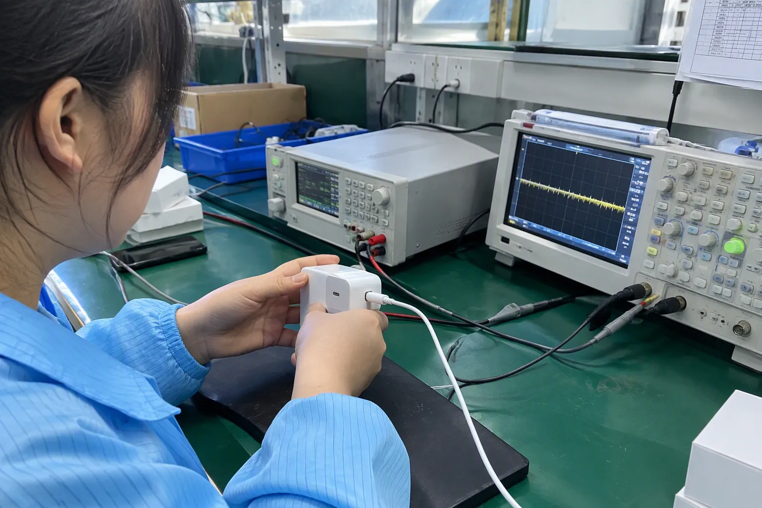
Many buyers see “ripple” on a charger report and assume that it describes the full quality of the power supply. That assumption creates risk. Ripple testing measures variation on the DC output under stated conditions[3], but it does not independently confirm electrical safety, protocol performance, component life, or regulatory compliance.
USB-C charger ripple testing measures the AC variation that appears on the charger’s DC output while the charger operates at a specified voltage, load, and measurement bandwidth. A credible result should identify the test conditions and show whether the output remains stable under that condition. The result should not be treated as a universal pass or fail number.
Ripple is only one part of output quality
A charger converts an AC input into regulated DC output. Its switching circuit, transformer, rectification stage, feedback loop, capacitors, cable connection, and load can all affect the waveform. The oscilloscope may display several types of variation, including:
I also distinguish between ripple, noise, and transient response when reviewing documents. Suppliers sometimes use these words interchangeably. A report may use a broad “ripple and noise” label even though the actual measurement includes switching spikes. I do not reject a report because of terminology alone, but I ask the supplier to define the method.
Why the output mode matters
A USB-C Power Delivery charger can negotiate different output profiles.[1] A small charger may provide 5 V at a basic condition and higher voltages at 9 V, 12 V, 15 V, or 20 V, depending on its design and advertised capabilities. The internal circuit may behave differently at each level.[2]
For example, a waveform taken at 5 V and light load cannot represent behavior at 20 V near the charger’s rated power. The switching duty cycle, current, thermal condition, and control response may all change. I therefore look for a test matrix rather than a single image.
| Report item | Why I need it |
|---|---|
| USB-C output mode | It identifies the negotiated voltage and advertised operating condition |
| Load current or power | It shows whether the charger was lightly loaded or tested near its rating |
| Peak-to-peak reading | It provides a numerical result for that specific test |
| Oscilloscope bandwidth | It affects which frequency components the instrument records |
| Probe connection | It can change the amount of measured high-frequency noise |
| Time window | It helps reveal whether the trace is steady or contains intermittent events |
| Sample identification | It connects the result to a specific model, revision, and unit |
What the waveform cannot prove
A clean trace does not prove that the charger has passed all applicable testing. It does not prove that the unit will survive shipping, high temperature, repeated insertion, abnormal input conditions, or long-term use. It also does not prove that the supplier’s certificate applies to the exact model and revision.
- Is the output waveform reasonably stable under the documented condition?
- Does the product meet the required USB-C and PD functions?
- Does the product meet applicable safety and electromagnetic compatibility requirements?
- Can the supplier control the same performance in mass production?
- Is the supplier’s evidence complete, current, and linked to the actual product?
Which Test Conditions Should a USB-C Charger Ripple Report Show?
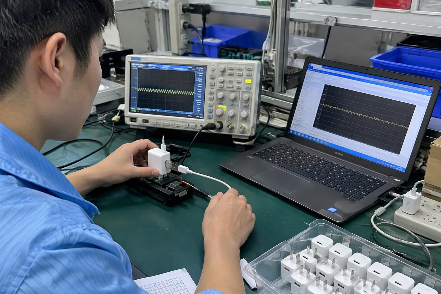
An incomplete report can make a mediocre result appear impressive. If I see only a voltage trace and a small number in the corner, I cannot tell whether the supplier tested the charger fairly. I need enough information to recreate the commercial meaning of the test, even if a qualified engineer performs the technical measurement.
A USB-C charger ripple report should show the tested output voltage, load current or power, input condition, oscilloscope settings, bandwidth limit, probe connection, time scale, vertical scale, sample identity, and test date. It should also state whether the reading represents a maximum, typical value, or single observed sample.
Voltage and load should appear together
| USB-C PD voltage | Load current | Load power | Ripple result | Test status |
|---|---|---|---|---|
| 5 V | Stated by supplier | Calculated | Stated by supplier | Test condition |
| 9 V | Stated by supplier | Calculated | Stated by supplier | Test condition |
| 15 V | Stated by supplier | Calculated | Stated by supplier | Test condition |
| 20 V | Stated by supplier | Calculated | Stated by supplier | Test condition |
Input conditions can change the result
The AC input may influence charger behavior.[8] A supplier may test at a nominal input voltage, while the target market requires a wider input range. European and American buyers may also have different expectations for mains compatibility and applicable compliance documentation.
Multi-port chargers deserve particular attention. A charger may show acceptable ripple on one port when the other port is unused, but its behavior may change when power is shared. A supplier should explain the allocation condition if the product has more than one output.
The report should identify the actual sample
I have seen supplier documents that use a model name but omit the hardware revision, sample number, or production date. That omission matters. A product may change its controller, transformer, capacitor supplier, firmware, or PCB layout without a visible change to the outside housing.
- Model and rated power.
- Hardware or engineering revision.
- Sample serial number or sample code.
- Production date or lot reference.
- Supplier name and laboratory name.
- Test date and responsible reviewer.
- Applicable test method, if one is being claimed.
I treat supplier-provided information as documentation to verify, not as independent validation. If the purchase is commercially important, I recommend that the buyer use an appropriately qualified laboratory or engineer to confirm application-specific requirements.
How Should I Read the Oscilloscope Trace?
A trace can look clean at first glance and still provide too little information for a procurement decision. I do not judge the line by appearance alone. I first check the measurement scales, waveform duration, reported value, and signs of intermittent behavior.
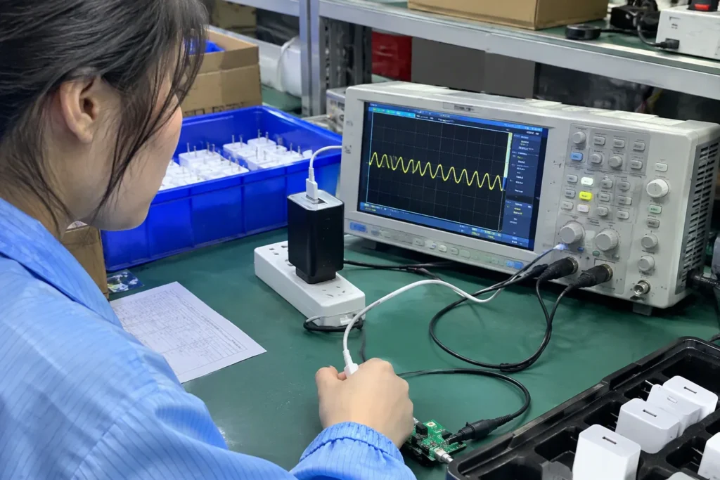
When reviewing a USB-C charger oscilloscope trace, I look for the stated peak-to-peak value, stable DC output, visible switching or high-frequency events, time scale, voltage scale, and bandwidth setting. I also check whether the probe connection may have added or removed noise. The trace must be interpreted with its test conditions.
Peak-to-peak is not the whole story
One waveform may show a regular, low-amplitude switching pattern. Another may show a mostly flat line with occasional sharp spikes. Both could produce a similar numerical reading inside one time window. The second pattern may require further engineering review because intermittent events can be hidden by a short capture or an unsuitable scale.
- Was the value measured automatically by the oscilloscope?
- Was the measurement taken over the entire displayed time window?
- Did the operator remove abnormal events from the reading?
- Does the report show typical and worst observed results?
- Was the charger tested after reaching a stable temperature?
Bandwidth changes what the instrument sees
An oscilloscope bandwidth limit filters high-frequency content.[4] A wider bandwidth may display more noise and ringing. A lower bandwidth may produce a smoother-looking trace while excluding some components.[5] Neither setting is automatically correct for every evaluation.
That is why I want the report to state the bandwidth setting. If one supplier uses a bandwidth limit and another does not, their ripple readings may not be directly comparable. I would ask both suppliers to clarify the method before ranking them.
The same issue applies to sampling and record length. A short capture may miss a rare event.[6] A long capture may reveal a change during load regulation or a repeated burst pattern. I do not expect a commercial buyer to design the test, but I do expect the supplier to document it clearly.
Probe connection can create misleading noise[7]
This does not mean that I can declare a reading wrong by looking at a screenshot. It means I treat the probe setup as essential evidence. The report should describe whether the supplier used a short ground connection, a suitable fixture, or another verified method.
| Trace feature | Possible interpretation | What I request next |
|---|---|---|
| Regular small variation | Normal switching-related behavior may be present | Confirm mode, load, and bandwidth |
| Sharp repeated spikes | High-frequency events may require engineering review | Request probe method and expanded trace |
| Occasional large peaks | The short test may not represent the whole condition | Request longer capture or repeat data |
| Different traces by voltage mode | Operating point affects regulation | Request a complete mode matrix |
| Very smooth trace with no settings | Evidence is incomplete | Request original report details |
How Can Buyers Compare Ripple Results From Different Suppliers?
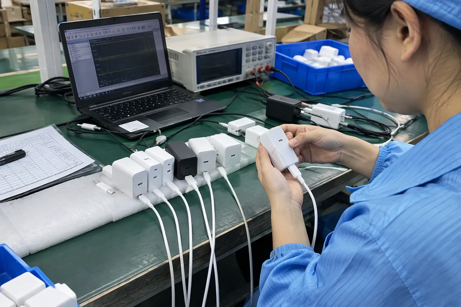
Supplier comparison becomes unreliable when each company uses a different test format. One supplier may send a laboratory-style report, while another sends a screenshot from a production workstation. A lower number does not necessarily indicate a better charger if the conditions are not equivalent.
I compare USB-C charger ripple results only after normalizing the key conditions: output mode, load, input, bandwidth, probe connection, time scale, sample identity, and test method. If those conditions differ, I record the results as non-comparable and request clarification instead of selecting the lowest number.
Build a supplier evidence matrix
| Evaluation point | Supplier A | Supplier B | Buyer comment |
|---|---|---|---|
| Exact model and revision | Provided / missing | Provided / missing | Match the quotation |
| PD voltage modes tested | Include relevant advertised modes | ||
| Load values | Record current and power | ||
| Input voltage and frequency | Check target market | ||
| Bandwidth setting | Confirm comparability | ||
| Probe connection | Request method description | ||
| Number of samples | Avoid relying on one unit | ||
| Other test reports | Verify model and date | ||
| Production controls | Ask how consistency is monitored | ||
| Warranty and corrective action | Put commitments in writing |
Ask for the original evidence
- “Please provide the test conditions for every displayed waveform.”
- “Please identify the output voltage and load current.”
- “Please confirm the oscilloscope bandwidth and probe connection.”
- “Please provide results for the major USB-C PD modes.”
- “Please link the report to the quoted model and hardware revision.”
- “Please explain how production units are checked against the approved sample.”
Compare quality systems, not just screenshots
- Incoming inspection for key components.
- PCB assembly controls.
- Functional output and PD protocol tests.
- Burn-in or sample reliability testing, where relevant.
- Final inspection records.
- Change-control procedures.
- Defect classification and corrective action.
- Packaging and shipping controls.
I also verify documents such as safety reports, EMC reports, and market-specific certifications against the exact model. Buyers should not assume that a certificate for one charger applies to another wattage, plug version, or internal revision. Official information from organizations such as the USB-IF and relevant market authorities should be checked for current requirements. For European products, buyers can consult the European Commission product safety and compliance information. For the United States, applicable requirements should be checked with the FCC and other responsible authorities.
Can Ripple Testing Prove a USB-C Charger Is Safe?
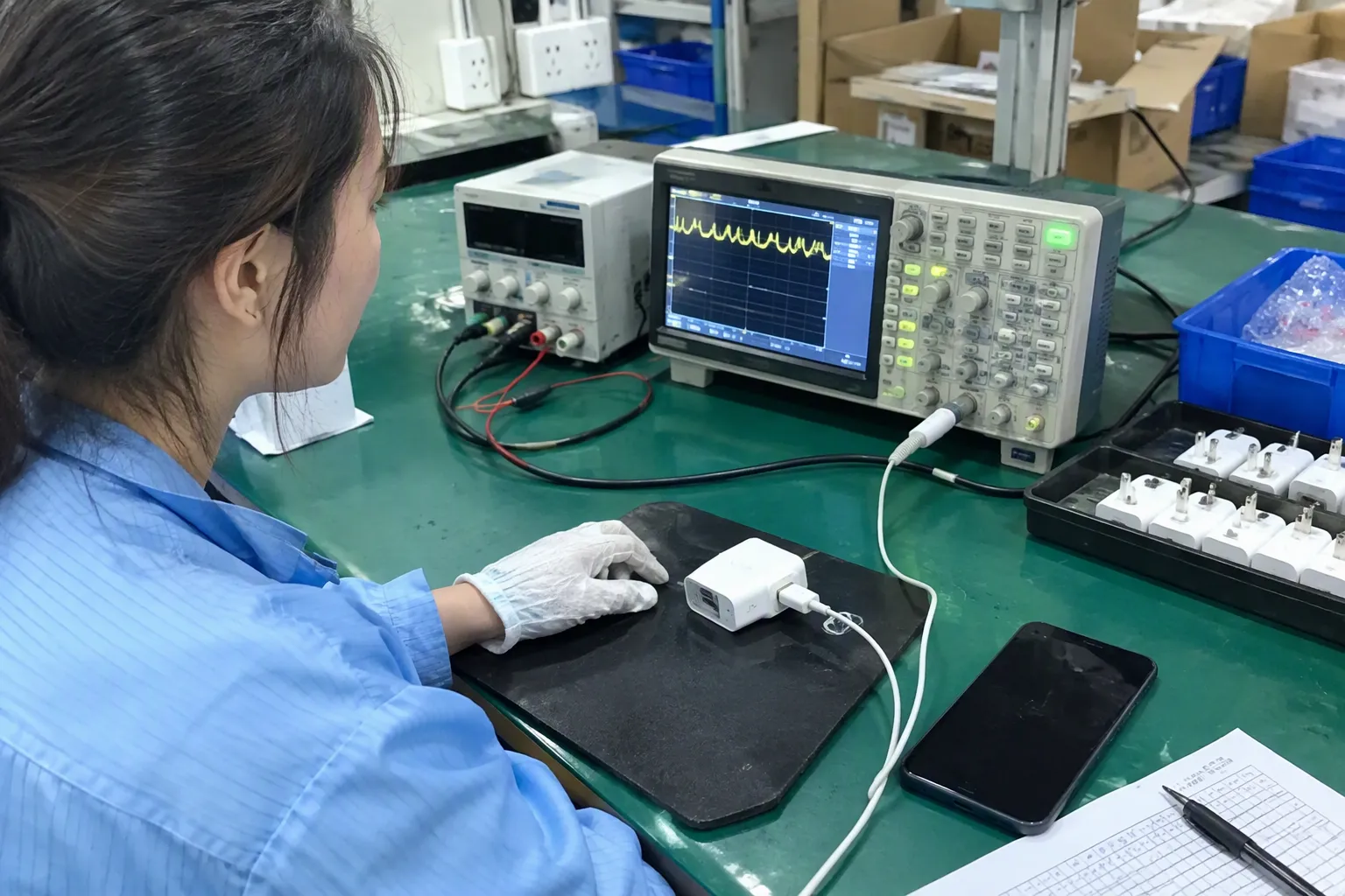
A supplier may describe a low ripple value as proof that a charger is safe. I would not accept that conclusion. Safety depends on insulation, creepage and clearance, component ratings, thermal behavior, protection functions, enclosure design, abnormal conditions, and applicable product standards.
USB-C charger ripple testing cannot prove overall safety, certification, or long-term reliability. It can provide useful information about output behavior under a defined condition. Buyers should combine it with verified safety and EMC documentation, product samples, functional testing, factory controls, and qualified professional evaluation.
Separate the quality questions
| Evidence group | Main question |
|---|---|
| Output regulation | Does the charger provide the expected output under documented loads? |
| USB-C and PD function | Does the charger negotiate and deliver its advertised profiles? |
| Electrical safety | Are insulation, protection, construction, and abnormal conditions adequately evaluated? |
| EMC behavior | Does the product meet applicable emissions and immunity requirements? |
| Thermal performance | Does temperature remain suitable under relevant operating conditions? |
| Reliability | Has the design been evaluated for expected use and environment? |
| Production consistency | Can the supplier reproduce the approved design? |
| Commercial execution | Can the supplier meet MOQ, lead time, packaging, and after-sales terms? |
Check documents with the exact product
- Does the report identify the same model as the quotation?
- Does the certificate cover the same power rating?
- Does the plug version match the destination market?
- Does the document refer to the same factory or legal manufacturer?
- Is the report current enough for the planned order?
- Has the supplier disclosed any component or PCB changes?
A document may be genuine and still be irrelevant to the product being purchased. I therefore recommend verification through the issuing laboratory, certification database, or qualified compliance professional when the order carries significant regulatory or commercial risk.
Use samples and independent checks appropriately
- Review the supplier’s technical file.
- Evaluate representative samples.
- Confirm critical electrical and protocol functions.
- Use a qualified laboratory for required tests.
- Approve a documented golden sample.
- Define production inspection and change-control requirements.
- Retain records for future comparisons.
What Should I Ask a USB-C Charger Supplier Before Approval?
A supplier’s response to technical questions can be as informative as the report itself. A capable supplier may not have every answer immediately, but the company should be able to identify the test source, clarify missing conditions, and provide a path to verification.
Before approving a USB-C charger supplier, I ask for complete ripple-test conditions, multi-mode results, product identification, applicable compliance documents, sample evidence, production quality controls, change notification, warranty terms, and a clear response to unexplained waveform differences.
Questions about the waveform
- Which USB-C PD voltage was tested?
- What load current and power were applied?
- Was the load constant, variable, or electronic?
- What input voltage and frequency were used?
- What bandwidth limit and time scale were selected?
- How was the probe connected?
- How many samples were tested?
- Was the trace captured before or after thermal stabilization?
- Were multiple ports active?
- Is the displayed result typical, maximum observed, or a single sample?
Questions about manufacturing control
I want to know how the supplier protects the approved design after sampling. I ask whether the factory performs output tests, PD negotiation checks, visual inspection, and safety-related production checks. I ask how it records failures and whether it can provide anonymized inspection examples.
- Minimum order quantity.
- Sample and tooling charges.
- Standard production lead time.
- Peak-season capacity.
- Packaging and labeling options.
- Warranty period and response process.
- Spare or replacement policy.
- Engineering-change notification.
- Responsibility for customer complaints.
These points are important for European and American retailers, wholesalers, and online sellers. A charger that looks attractive in a sample review may still create problems if the supplier cannot support replenishment or handle field complaints.
A practical approval decision
| Supplier response | My procurement view |
|---|---|
| Complete conditions, traceable model, consistent samples, verifiable documents | Suitable for deeper technical and commercial evaluation |
| Partial report but cooperative clarification and reasonable samples | Keep under review; request corrective evidence |
| Low number only, unclear model, missing settings, pressure to approve quickly | Do not use the screenshot as approval evidence |
How Does Ripple Fit Into the Final Supplier Decision?
Procurement teams often need a practical answer. They cannot spend unlimited time on every product, yet they should not approve a charger from one polished image. I use ripple testing to identify questions and compare documented conditions, then I combine it with commercial and quality evidence.
USB-C charger ripple testing is most useful as part of a supplier evaluation framework. I use it to assess whether output behavior has been documented consistently, while I use samples, compliance records, production controls, and supplier communication to judge whether the product is suitable for further approval.
Use a risk-based review
- Product wattage and number of ports.
- Target market and regulatory obligations.
- Expected order volume.
- Connected equipment sensitivity.
- Retailer warranty exposure.
- Custom branding or enclosure changes.
- Supplier history and previous quality issues.
- Whether the product is a new design or an established model.
Keep commercial requirements visible
Technical evidence is important, but procurement also needs to evaluate whether the supplier can deliver the business requirements. I discuss MOQ, lead time, packaging, branding, payment terms, spare units, and after-sales support early in the process.
My company has worked with 3C export products such as USB cables, chargers, GaN chargers, TWS earbuds, and smartwatches for European and American markets. In that work, I have seen that buyers usually want a balance of stable quality, competitive pricing, modern designs, and dependable delivery. A supplier review should reflect that complete picture.
I use internal references such as our guides to choosing a USB-C charger supplier, checking charger compliance documents, and planning a 3C product quality inspection to keep discussions organized. These links should support the buyer’s process, not replace independent technical verification.
Create an approval record
- Approved quotation and specification.
- Sample photographs and identification.
- Ripple reports with conditions.
- Functional test results.
- Verified compliance documents.
- Packaging and labeling approval.
- Inspection plan.
- Supplier corrective-action commitments.
- Change-control agreement.
- Final commercial terms.
Frequently Asked Questions
What is a good ripple value for a USB-C charger?
There is no single value that proves every USB-C charger is acceptable in every application. The buyer should review the specified voltage, load, bandwidth, probe method, and product requirements. A qualified engineer should confirm the appropriate acceptance criteria for the intended equipment and market.
Should I request ripple results at every USB-C PD voltage?
I recommend requesting results for the main advertised PD modes, especially the modes that matter to the target devices. A charger can behave differently at 5 V, 9 V, 15 V, and 20 V. One test condition should not represent the complete output range without supporting evidence.
Can a clean oscilloscope screenshot prove charger safety?
No. A clean screenshot only shows the measured output behavior under a stated or sometimes unstated condition. It does not prove insulation, thermal safety, EMC compliance, protection performance, certification validity, or long-term reliability.
Why do two suppliers report different ripple results?
The suppliers may use different output modes, loads, input conditions, bandwidth limits, time windows, or probe connections. They may also test different hardware revisions or samples. I first normalize these details before treating the numbers as a meaningful comparison.
Should a buyer perform the oscilloscope test personally?
A buyer does not need to become a laboratory engineer to review supplier evidence. However, the measurement should follow a verified method and may require qualified technical support. The buyer should focus on obtaining complete records and using an appropriately qualified professional for application-specific decisions.
Conclusion
USB-C charger ripple testing can provide useful evidence, but I never use one low peak-to-peak number as proof of product quality. I check the voltage mode, load, input, bandwidth, probe connection, time scale, sample identity, and test scope. I then compare that information with samples, verified compliance documents, production controls, and supplier support. If you are sourcing USB-C or GaN chargers for European or American markets, contact me to discuss supplier screening, sample evaluation, MOQ, lead time, customization, and a practical quality-review plan.
Sources
- USB Power Delivery", The USB Power Delivery specification defines a negotiation procedure through which a source and sink exchange capabilities and select an operating power contract, including supported voltage and current levels
- DC-DC Power Converters", Power-converter studies describe operating-point dependence in switching frequency, duty cycle, current stress, efficiency, and control response, providing a mechanism by which output behavior can differ across voltage and load conditions
- AN-1144: Measuring Output Ripple and Switching ...", Power-supply measurement literature defines output ripple and noise as time-varying voltage components present on a nominally regulated DC output, with the reported result depending on the specified load and measurement bandwidth
- Why do oscilloscopes have bandwidth limits?", Oscilloscope measurement references describe bandwidth as the frequency range over which the instrument preserves signal amplitude within a specified response, so applying a bandwidth limit reduces the displayed contribution of higher-frequency components
- Oscilloscope noise and 20 MHz bandwidth limit", Measurement studies show that bandwidth restriction can attenuate high-frequency noise, spikes, and ringing, producing a visually smoother waveform and a different measured peak-to-peak value
- Oscilloscope Fundamentals", Oscilloscope measurement guidance notes that event detection depends on acquisition duration, sampling, and triggering; an event that occurs outside a short acquisition record will not appear in the captured waveform
- Introduction to Oscilloscope Probes: Instructor's Guide", Oscilloscope-probing guidance explains that long ground connections and large loop areas can introduce inductive pickup and ringing, causing the displayed high-frequency waveform to differ from the voltage actually present at the measurement point
- How to Measure Ripple Voltage on a Switch-Mode Supply", Power-converter analyses indicate that line-voltage and line-frequency conditions alter the rectified input waveform and converter operating point, which can affect regulation, ripple, efficiency, and component stress